Tuning my D3 Rotatable Dipole

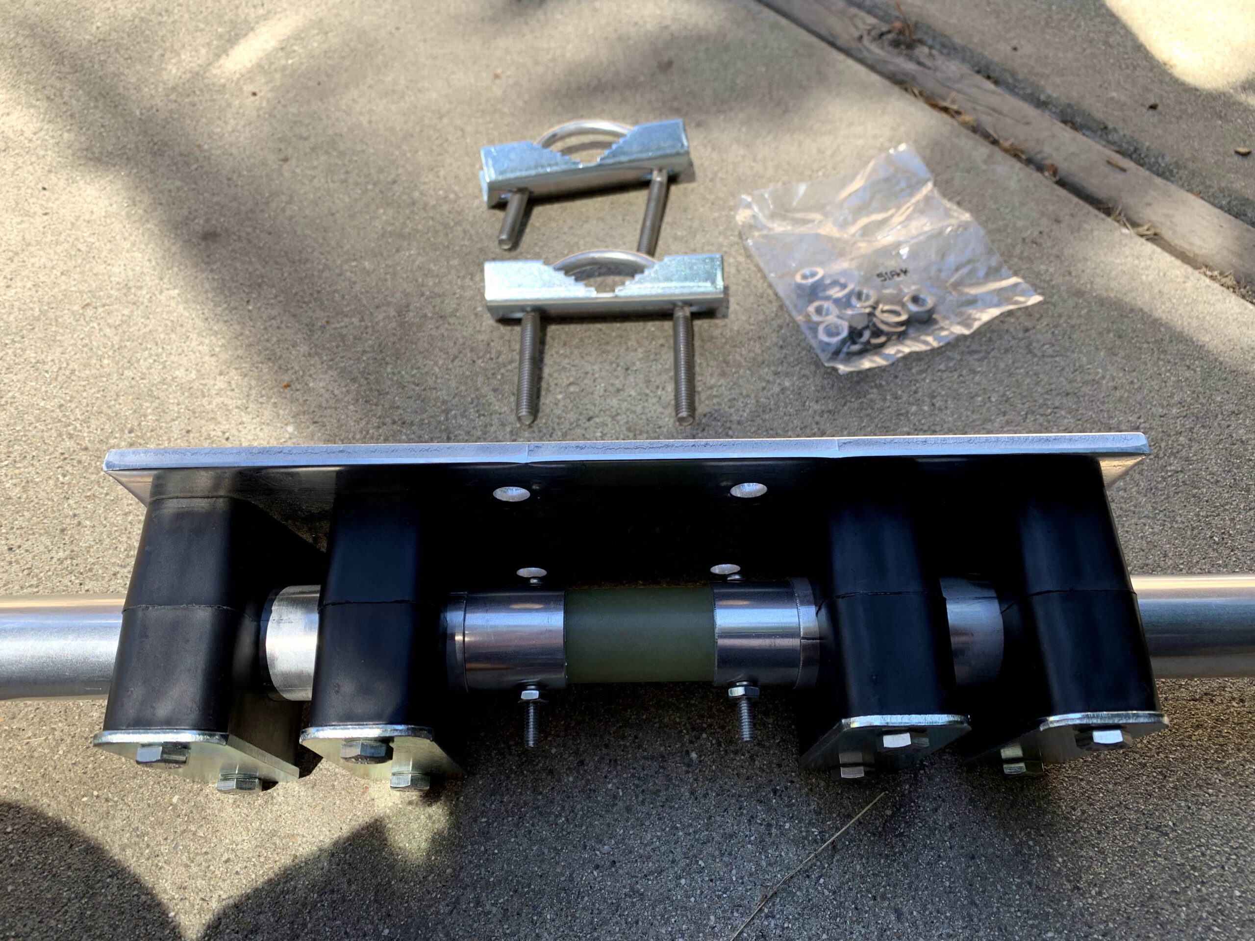
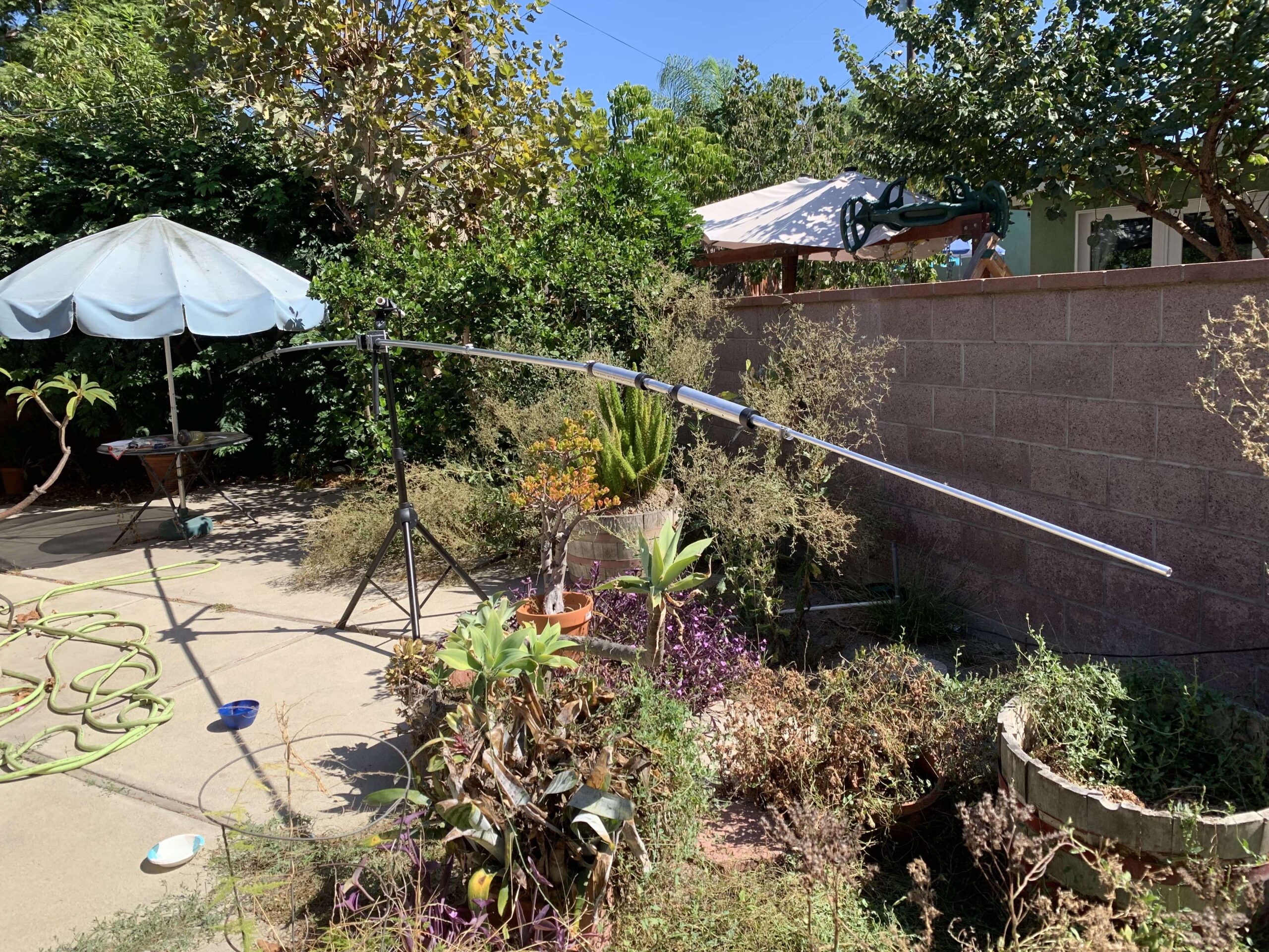
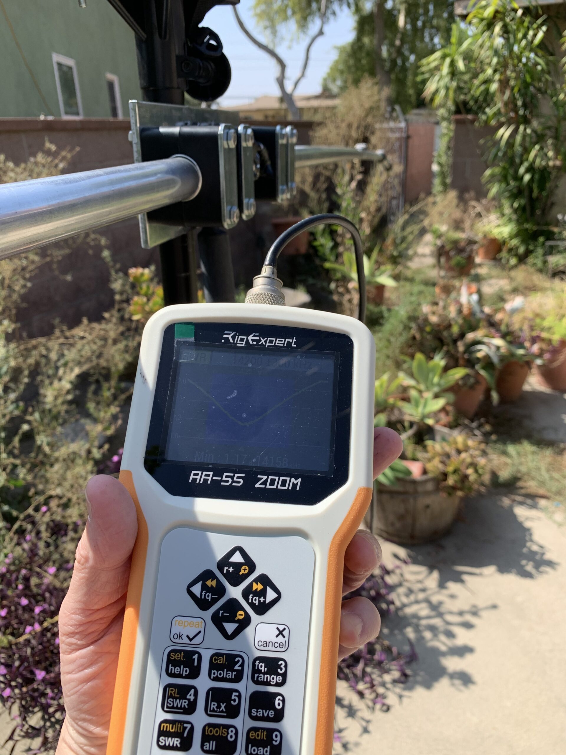
Once assembled, used a RigExpert AA-55 Zoom to analyze the SWR and help tune the antenna. Between the coax connector and the analyzer is the same RF choke that will be used once the antenna is put up. Started lengths close to Cushcraft’s suggested lengths for the middle of each band. My thinking is to adjust the length to the first trap focusing on 10 meters, then move outward to the next trap for 15M, and finally to the total element length for 20M.

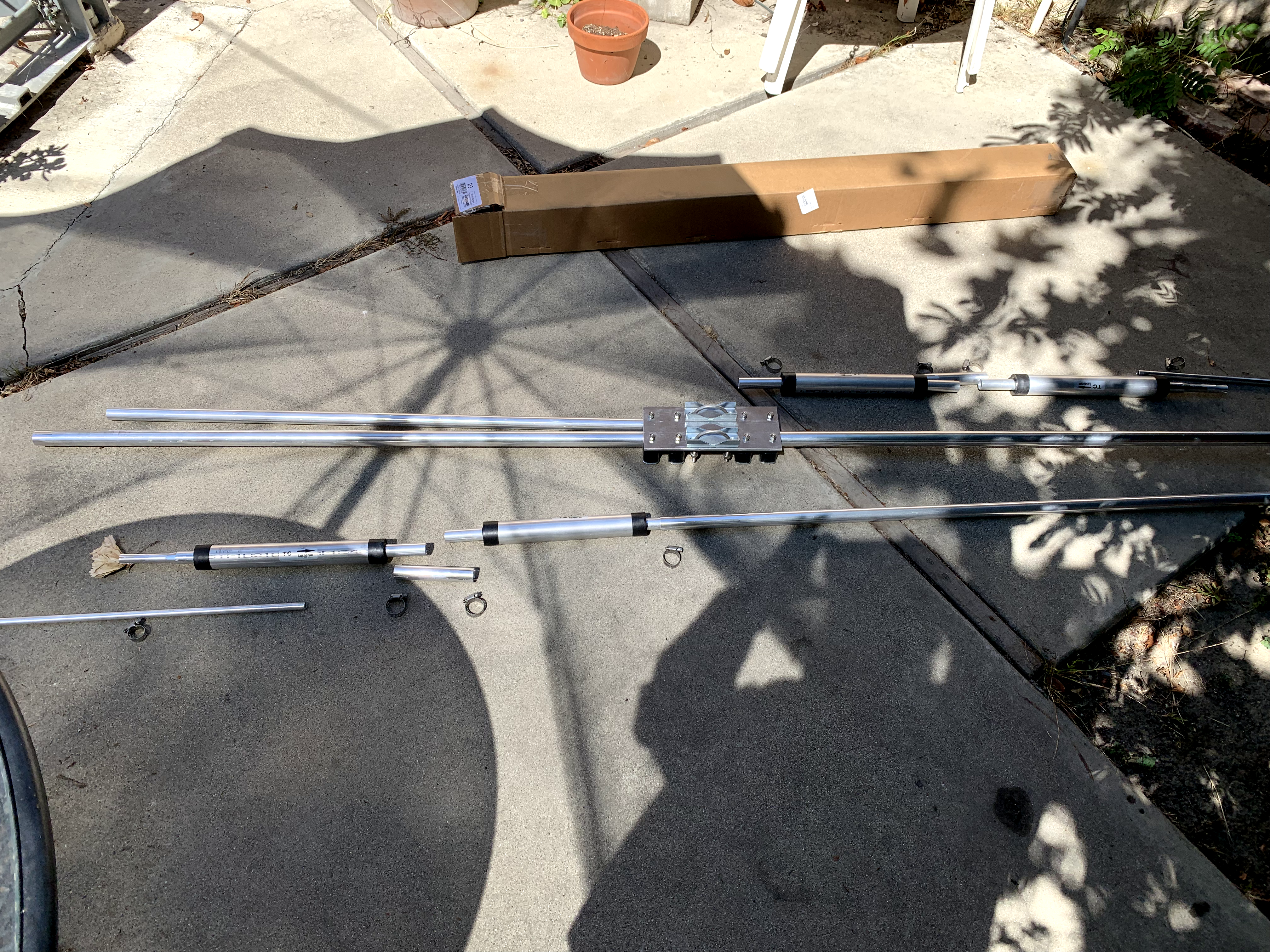
Drew out a diagram showing the element lengths to be adjusted.

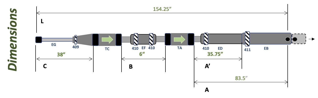
  • Length A is the distance from the coax connection screw to the black edge of the first trap.
  • Length A’ allows for easier measuring. A’ is the length from the end of the first piece of aluminum tubing to the black edge of the first trap (start of the trap. Thus, A is consistently 47.75 inches longer than A’ since the length from the coax connection point to the end of the tubing is that length. This made it much easier to measure than the full distance of A.
  • Length B is the distance between the end of the first trap (the outward black edge) to the start of the next trap (again, the black edge, not the aluminum tubing).
  • Length C is distance from the outer black edge of the last trap to the end of the aluminum tubing at the end of the element.
  • Length D is the total length of the element, from the ending tip of the left side all the way to the ending tip of the right side. In my table, this is a calculated value (other than a quick measurement to validate my math). I used this value, along with A, B, & C, to compare with the manufacture’s specifications.
  • Length L is for my use, again as a check of my math, from the coax connection screw to the end of that side. Note that there is 1 inch between the coax connection screws, and D equates to 2 times L plus one inch.

Below is a chart of the lengths and measured center frequency at that length.

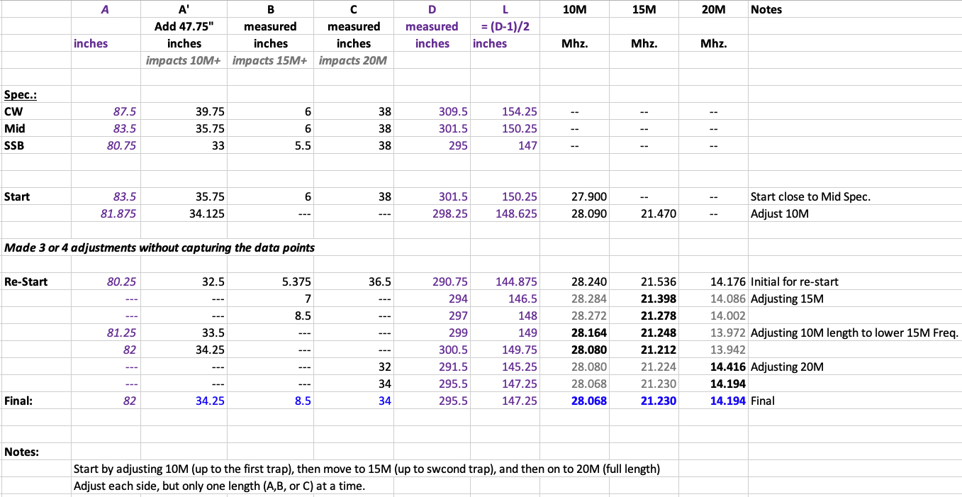
Each of the bands is now useable. The tuniing for 20M is exactly where I wanted it. For 15M, it is a little high , and 10M is lower than desired; however, all the bands will be usable with an SWR below 2:1.

After making all the adjustments and measurement, the clamps were tightened and measurements were re-taken with no significant changes to their values.

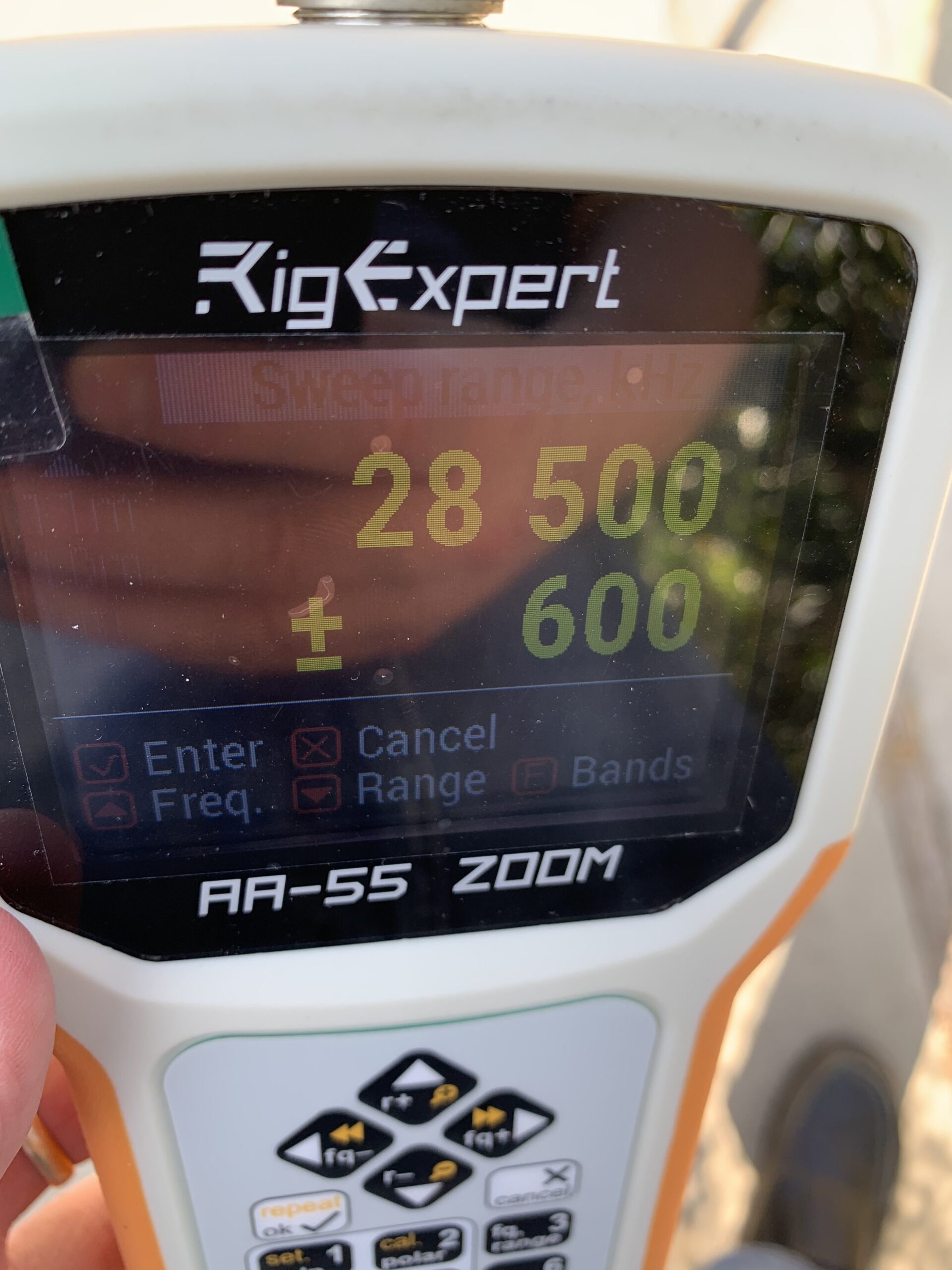
10M measurement settings: 28.500 Mhz. +/- 600 hz.

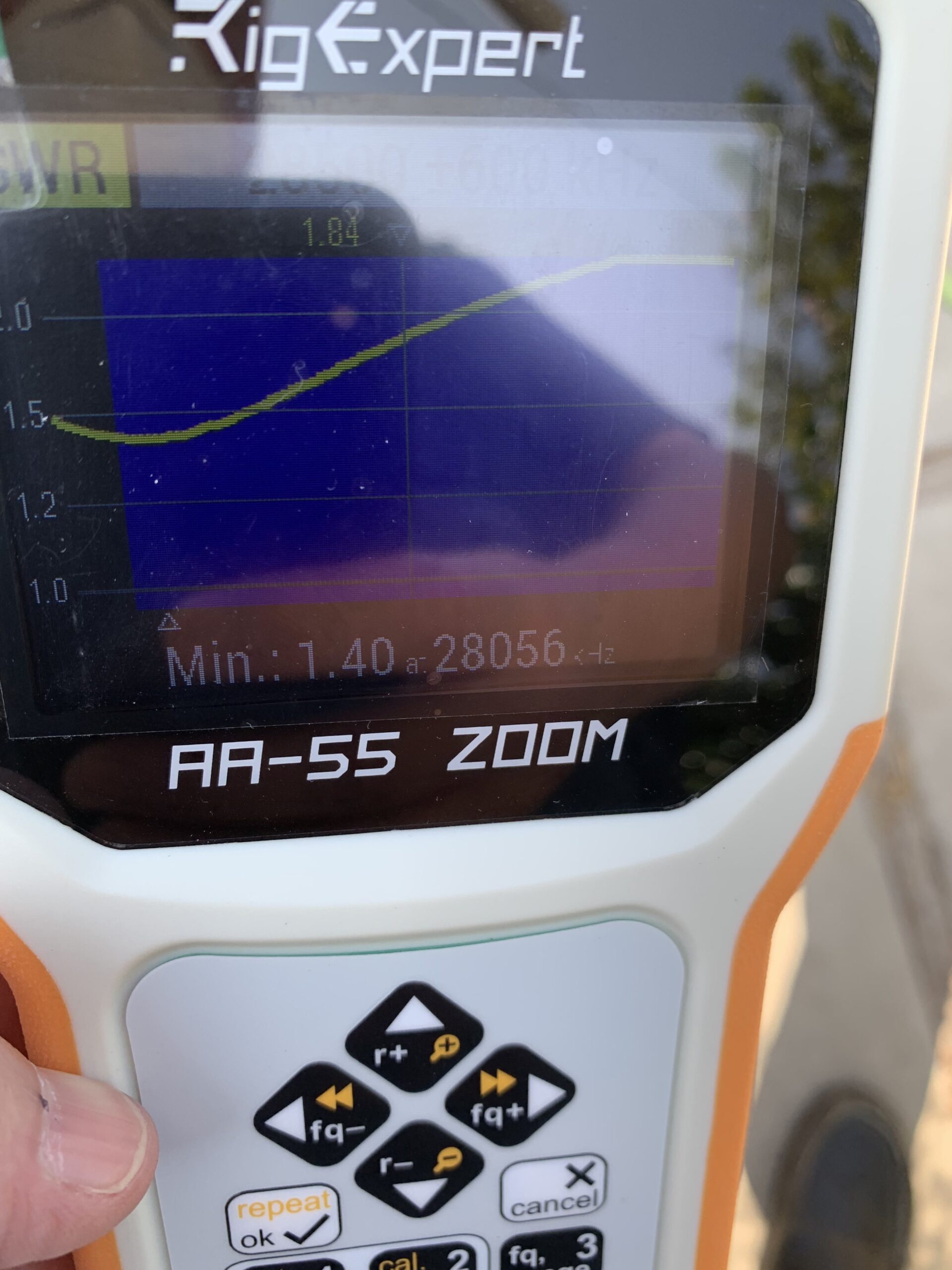
Center Frequency showed: 28.056 Mhz.
Usable band is from 28.000 Mhz. up to 28.600 and possibly a little bit more. This works well for where I operate.

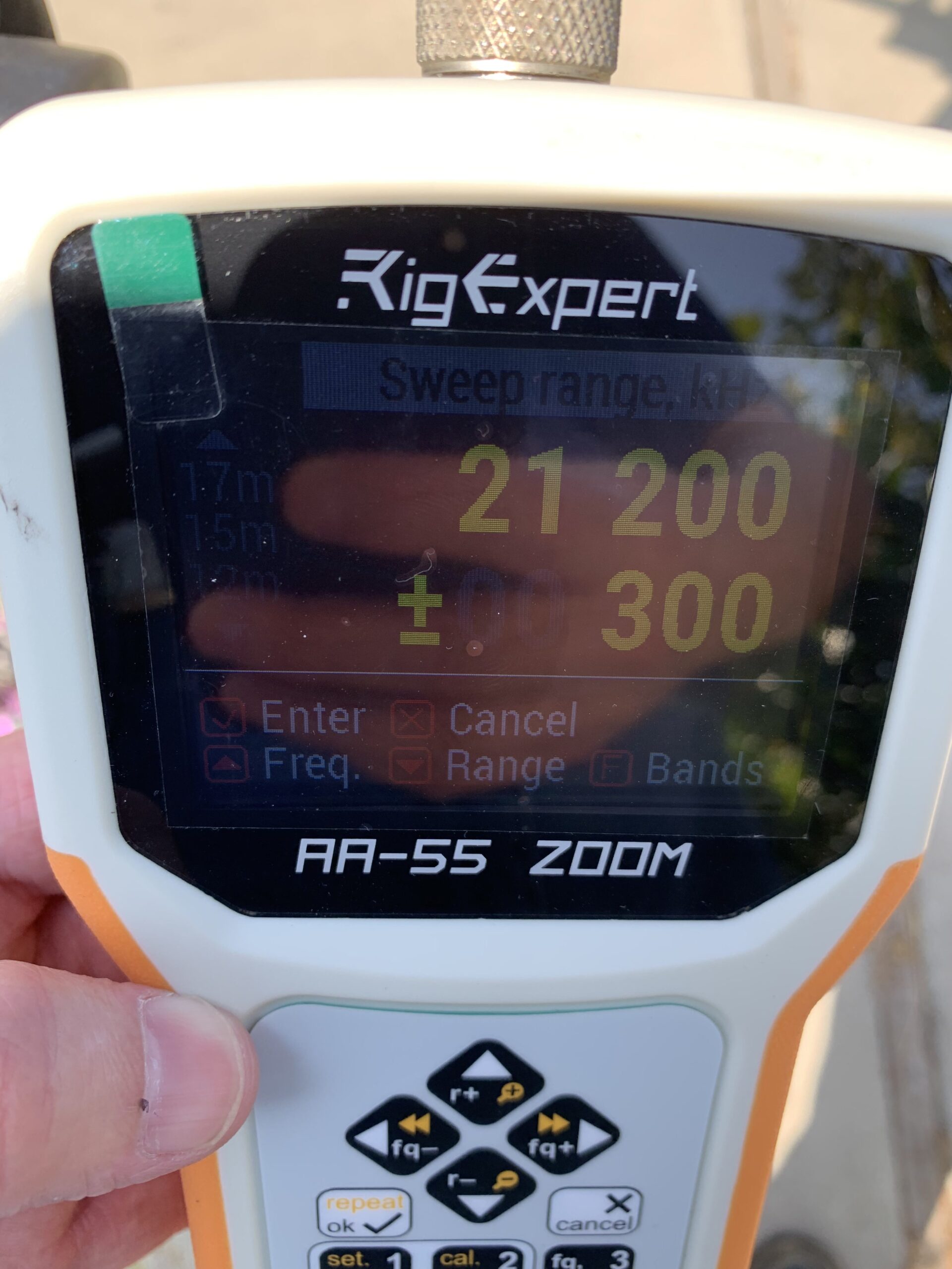
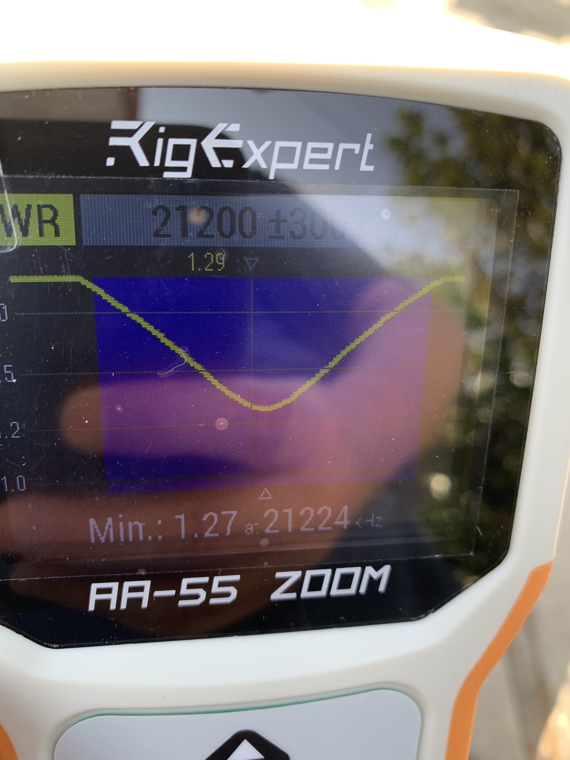
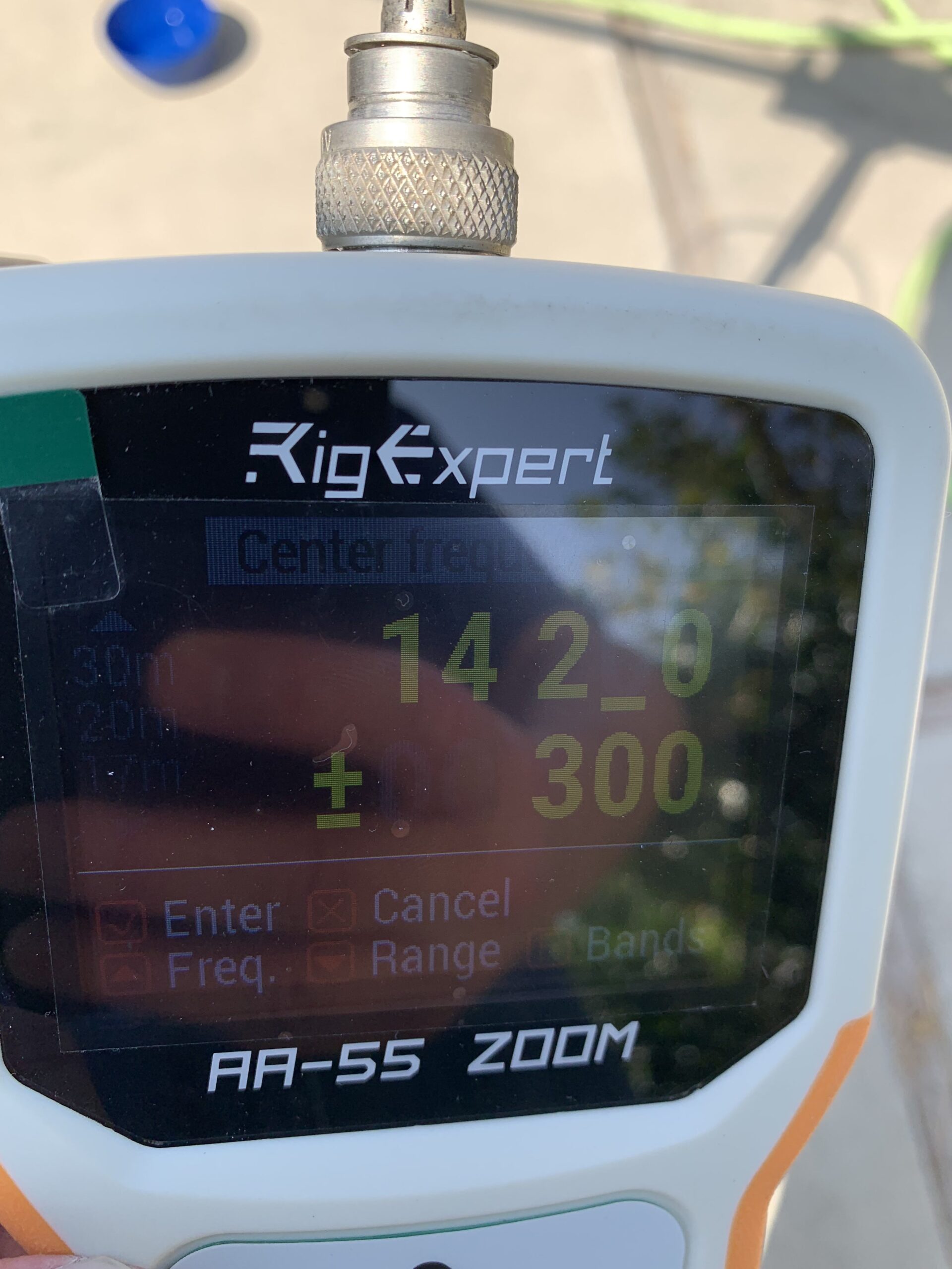
15M measurement settings: 21.200 Mhz. +/- 300 hz.

Center Frequency showed: 21.224 Mhz.
Although the low and high ends have a higher SWR than I would like, the antenna will be usable across all of 15M.

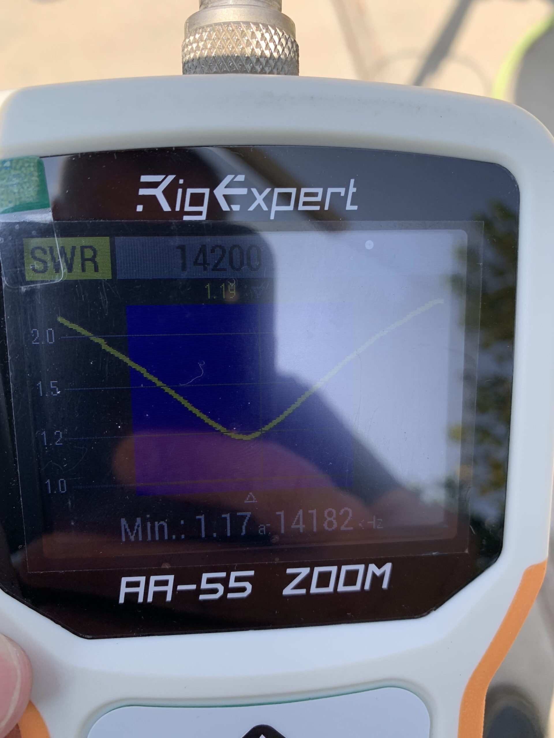
20M measurement settings: 14.200 Mhz. +/- 300 hz.

Center Frequency showed: 14.182 Mhz.
The dipole will be usable across the entire band.

The D3 rotatable dipole is tuned and ready to be put up & on the air.


Posted in General, Radio | Leave a comment

Assembly of Cushcraft D3 Rotatable Dipole

My existing Yagi for 10/15/20 meters has high SWR due to at least one damaged trap (operator error, but that is another story). Until I can either replace or repair the beam, decided to put up a Cushcraft D3 Rotatable dipole. There are a couple of options for where to put it, but first, it needed to be assembled. the following is my experience in putting it together, told in pictures.

Started with the unopened box.

Set out all the parts received.

Screw clamps will use a 5/16 inch nut driver. Common tools were all that were needed for assembly. All tools shown are my tools, and were not included with the D3 (as expected).

Begin Assembly by attaching the fiberglass center piece to the larger aluminum element part.

The center piece takes an 11/32 inch wrench. Note, later the coax will connect to these same screws.

Ready to put together the base plate assembly. The black pieces will insulate antenna from the base plate.

These nuts required a 7/16 inch wrench.

Attached the U-bolts that will later connect to the mast.

U-bolt nuts use a 1/2 inch wrench.

Base plate assembly is now complete, ready for the coax & mast.

The aluminum tubing and traps were set out and put together using the screw clamps. The traps have arrows that need to point to the center. Also, the traps have holes that will need to be pointed downward to allow moisture to drain out from them.

From the center connector, the first trap is the TA trap that will isolate 10 meters. The second trap is the TC trap that will isolate 15 meters. And 20 meters will use the entire length of the antenna.

All the pieces were put together and using a speaker tripod stand, it was set up in the backyard for tuning. Once tuned, it will be put up 30 to 40 feet in the air.

After the antenna was tuned, the end caps were put on. Left these off to make measuring easier until tuning was done.

Posted in General, Radio | Leave a comment

Arduino Satellite Antenna Rotator Project

After looking around for a portable satellite antenna rotator , I came across the School Amateur Radio Club Network website with instructions on how to build one for a low cost using an Arduino. Their site has excellent instructions. Below are pictures and descriptions of my experience building this fun project.


Initial parts

The parts above include the Pro Micro Arduino. Just below the box is one of the ones that came in the package. To the left of it is the motor controller board. It will control the 2 motors. Below the motors are some mounting parts to connect the motor shafts to the antenna and tripod.

The Arduino software was downloaded. I did a quick test, loading a minimal example program and verifying that the board worked & that the computer could talked to it.

Magnetometer / Accelerometer Board

The Magnetometer / Accelerometer board took a few weeks to come after ordering.

Template for drilling holes for motors

Used an index card and a pointy screwdriver to make a template for drilling the holes in the case.

Rotator Box with raised area ground off

After carefully measuring multiple times to center each shaft, the holes were drilled for the motors, motor controller board, the Arduino. However, the box had these raised areas for screw attachments that precluded the azimuth motor from fitting properly in the box. The top center part of the picture above shows where one of the raised areas had to be ground off.

Azimuth and Elevation motors fit in the box

After re-working the box, the motors fit well. The holes drilled from the template are just right.

Arduino ready for soldering
One last view before I attempt to soldier those tiny pins

I decided to use the pins and push on wires rather than soldering wires directly to the Arduino and magnetometer boards. Above, the board has the pins pushed onto the board and the other end of the pins are pushed into the breadboard to hold everything in place.

Arduino with pins poorly soldiered

Well, that did not go so well. Most of it looks good, but some of the pins pulled away and the soldering job is not the best. I had better not give up my day job…

The Magnetometer / Accelerometer board is to be soldiered next

Ok, let’s try this again. Next is the magnetometer / accelerometer board.

The Magnetometer / Accelerometer board on breadboard

Once again, used a breadboard to hold the pins in place even though the pins were only on one side of the board.

The Magnetometer / Accelerometer with pins soldiered

That went much better. I am happy with this soldering job.

Arduino and Magnetometer / Accelerometer boards

Now these are ready to be connected.

Wires to be make and the wires that were made

Drew out the wires and made any remaining connectors. In the of the above picture is a 4-pin DIN connector, which is used to connecting the Magnetometer / Accelerometer board.

Wires inside rotator box

Mounting motor controller board (upper right of case above) had similar issues as the motors had. The case had raised area. Stand off mounting had to be longer than planned to make it fit past the bump. The wires were connected. The Arduino board was left floating – without any mounting. On the bottom right of above picture, the USB connector and 12V power pole connectors are routed out of the box.

Magnetometer / Accelerometer board with wires attached

The wires were attached to the Magnetometer / Accelerometer board.

Completed rotator box ready for mounting to tripod & antenna

With the wires connected, the box was closed up. Performed a quick test to verify the USB cable was working and the Arduino board was still working.

The next steps are: (1) calibrate the Magnetometer, (2) attach the azimuth shaft (on the side to the bottom left of the above picture) to a tripod, (3) attach the elevation motor shaft (coming out of the top of the box) to the boom for the Arrow Antenna, and (4) attach the Magnetometer / Accelerometer board to the boom.

To be continued…

Posted in General | Leave a comment

Computer WinKeyer Software & Transceiver Connection

The Mac laptop was connected to the WinKeyer using a USB cable. As it was attached, the keyer sent an audible “R”.

At the time I am writting this, the MacBook Pro laptop computer that I am using is running macOS Sierra, Version 10.12.3

In December, the Windows computer that I had been using had a power supply failure. It was still running Windows 95 and overdue for replenishment. My main computer upgraded to Windows 10, but it was a bit older and the new operating system brought it to a crawl. I replaced both of the computers with a single Mac laptop and two docking station setups.

The radio room computer had been connected via a serial port to a RigBlaster Pro for RTTY, and the parallel port was connected to the FT-990 as a key. I was running Win-Test, and CT back in the days of DOS. Having a Mac computer, no serial port, and no parallel port, The setup needed to be changed. After some discussions with others and looking around the internet, I choose to use a WinKeyer3 USB and to try out a couple of contest logging programs. Once that worked, I would look into re-setting up the RTTY interface.

The existing RigBlaster is connected to a microphone, the radio audio input, and the radio push to talk. It has a push-to-talk input on the back. I decided to make it simple for now, and attach the PTT from the keyer to tto the input PTT on the RigBlaster. I unplugged the straight key and used an existing cable (taking up space in a spare parts drawer) to connect the WinKeyer Key output to this radio key input.

MacWinKeyer

The software “MacWinKeyer” was downloaded and installed. It ran fine, and had a number of options. After looking through the available settings in the various menus, I left it close to the original defaults. Below are the settings used (I do not remember which are the defaults, and which ones I changed.):

Serial Port Settings:

  • Used the middle selection menu, and set it to the setting closest to “usbserial-A1025HQ3”
  • Clicked the Open Port button.
  • At the bottom left, the dots in the red circle went around for a second or two, then it turned green. The keyer was connected.

Host Mode Settings:

  • I did not change most of the default settings.
  • Under the Paddle area, I set the Mode to “Iambic A” (not sure if that made any difference).
  • Sidetone box
    • selected “Enable Sidetone”
    • Left the setting to “500 Hz”
  • Push To Talk box
    • Selected “Enable PTT”
    • Did not select SO2R Mode (Single Op, 2 Radio)
  • Keying box was left the same
  • Host
    • Selected Paddle Echo
    • Selected Serial Echo
  • Messages
    • Here is where I entered my messages for testing
      • 1: “testing”
      • 2: “this is a test  de w6grv”
      • 3: “test 1 2 3”
      • I left the others empty (for now)

Host Mode:

  • Now it was time for the first test. Adjusting the physical knob on the WinKeyer, the value displayed at the top for the speed adjusted up and down.
  • Second test was to click the “Tune” button on the bottom left. The WinKeyer put out a tone until the Tune button was clicked again.
  • Next, I pressed the button for “Message 1 (F1)” and it sent “TESTING” as expected. Messages 2 and 3 sent the values entered from before (“THIS IS A TEST  DE W6GRV” and “”TEST 1 2 3”).
  • I then played with echo mode, and it sent what I was typing as I typed it.

WK3 User 1 Standalone Mode Settings:

  • This area allows the user to store information into the keyer memory (EEPROM).
  • I left everything the same except the Messages area.
  • A couple of hings I learned were
    • After typing in a message, it needs to be written to memory (press Write EEPROM) before it worked.
    • If the cursor was still in the message entry field, the value was not written to memory and did not work.
  • Entered a few messages
  • Pressed “Write EEPROM”
  • Pressed “Play  1”, and the WinKeyer sent the CW using its’ speaker.
  • Now, pressing the buttons on top of the WinKeyer, the CW message for that button was sent. The keyer was programmed. Even when disconnected from the computer, it still remembered the message for each button.
    • This worked for Play 1 through 4

WK3 User 2 Standalone Mode Settings:

  • This worked the same as the WK3 User 1 Standalone Mode Settings.
  • Since I am connected to a WinKeyer3, the WK2 Standalone Mode Settings is greyed out.

Skookum Logger

Now to move on to setting it up to some contest logging software. Not knowing what to use, I thought I would try a couple of different programs to see what worked best for me. I installed Skookum Logger, and looked through the settings. There were a number of settings, but the defaults had most of what I needed.

A couple of notes (operator error):

  • General notes
    • Only one application can be connected to the USB device. So, having left MacWinKeyer running, the logging program couldn’t connect to the keyer.
    • The keyer did not make a sound, but was working fine. Once it was connected it to the transceiver, everything worked well.
  • Skookum Logger specific notes:
    • In “Preferences”, under the “Serial” tab,
      • Set “Radio 1” to “Phantom” if not using a radio interface. Without this set, I was unable to set the band when logging QSOs.
      • For Keyer, use “WinKeyer 2” since WinKeyer 3 was not an option. (this works fine). And in the Port pull down next to it, select the one closest to “usbserial-A1025HQ3”
    • In “Preferences”, under the “WinKeyer” tab, I left the settings as they were.

I was trying to test using the software with just the keyer before connecting the cables to the FT-990. This was a frustrating mistake. It was working, but the keyer stayed as quiet as a mouse. I was sure the keyer was working, but was almost certain that it did not work with this program. I finally decided to connect it to the radio to see if the Push-To-Talk worked. It did. Then I thought that perhaps the software turned off the WinKeyer internal speaker, and went ahead and connected it to the radio. Now when I tried sending code using the contest logging software, everything was working.

RUMlogNG:

I thought that I would try a second contest loggin program, RUMlog. Looking at the forum page on their home website, a new re-written version was available as “RUMlogNG”. The program installed and ran well.

  • Under “Preferences” and the “CW” tab:
    • CW Interface was set to “Winkey” and “K1EL”
    • Software CW memories
      • Entered CW message to send after F1 to F6
      • For the Button text, put in a brief entry to be button name text
    • Port was set to the one closest to “usbserial-A1025HQ3”
    • Selected PTT enable
    • Selected Key out 1 enable
    • Clicked the button “Apply Now”

After some brief testing, this was working contest logging program was configured and working.

Links:

MacWinKeyer: (Mac)

http://www.k1gq.com/MacWinKeyer/index.html


RUMlogNG: (Mac)

http://www.dl2rum.de/rumsoft/RUMsoft_Home.html


Skookum Logger: (Mac)

http://www.k1gq.com/SkookumLogger/


Win-Test: (Windows)

http://www.win-test.com/


Posted in Contests, General | Leave a comment

Assembling WinKeyer

Assembled WinKeyer USB

Assembled WinKeyer USB with the battery mounted on the side

I needed a CW interface between my Mac computer and TS-990 transceiver. It needed to be compatible with contest logging software, select push-to-talk, and transmit CW. Before I had used LPT1: on a PC, but needed to move to a USB interface. After talking to a few others and searching on line, WinKeyer USB appeared to be a good option.

WinKey US Box as received

WinKey US Box as received

The kit arrived on Friday and I printed out the online assembly instructions.

Parst out of the box

Parts fresh out of the box and still all nicely wrapped up

Saturday afternoon, I set out the tools, checked the parts against the parts list, and re-read the instructions.

Parts

Another view of the same parts

Verified I had all the parts in my work area. I noticed that the paddle connector came already attached.

Work area

Work area before getting started (the before picture)

Set out the tools. (I had to make one extra trip to get a pair of scissors to open the packages.) The tools included a soldering iron, small flat head screwdriver (for putting on the knob), small Phillips screwdriver, something to be another pair of hands, and some fine solder.

Next step was to mount the USB connector, fold back the larger case stubs to hold it in place, and carefully solder the 4 small pins. These were the smallest and closest together of all the pins to be soldered. I did not do a very good job with these. I got the board too hot, and put too much solder on them. Fortunately, they were not shorted and nothing was damaged.

The small speaker was pushed into the board, being careful to point the positive listed on its’ paper covering in the right direction.

USB plug, RCA plugs, and Speaker

Shows the USB connector in top right, 4 RCA plug piece mounted on right center, and speaker in lower left with the paper cover still attached. In the center, the soldering I did to connect the 4 switches can be seen.

Once I got over my poor attempt at soldering the USB connector, I moved on to attaching the switches. These pushed into their holes on the board and almost felt like they snapped into place. I did bend one of the bins on one of the switches, but it was easy to bend back.

After soldering the switch pins (4 switches with 4 pins each), the white 4-connector RCA plug assembly was mounted and its’ pins were soldered.

Next, the four push button caps were snapped onto the to of the buttons. There were 3 black caps and one red cap. the Red cap went on the left most button with the buttons facing up and the RCA plugs facing away from me.

Back side

the back side has the 4 switches. On the bottom left is my poor soldering job when mounting the USB connector. On the center right, the 4 RCA plug assembly is mounted to the board, but not yet soldered.

The kit came with a 14 inch piece of wire. This was cut into two 7 inch wires for connecting the speed knob.

Speed Control wires

Wires soldered to the speed control

First these wire were connected to the know, and then soldered to the board.

Speed control wires

Speed control wires are soldered to board. To the left of the top switch in the picture are two solder connections for the speaker. On the right side, the RCA plug connections are now soldered.

Then the battery case wires were soldered to the board, and all the soldering was done.

Battery box is attached

Battery box is attached.

Four screws were provided to secure the PC board to the top of the case. Then the knob was fastened to the bottom part of the case.

Circuit board attached to case

Circuit board is mounted to the top part of the case with 4 Phillips screws. The speed control is mounted to the bottom part of the case.

The battery was supposed to go inside the case. I wanted to have easy access to the battery. My experienced is that batteries typically run down in the middle of a good run during a contest, and I wanted to easily be able to swap them out for new ones. The supplied Velcro was put on the outside of case. I may go back and drill/snip a hole in the case to run the battery wires out.

Back side of completed project

This is the back side of the completed kit. I choose to run the battery wires out of the back of the case and used the included Velcro to attach the battery case to the side.

The final part of assembling the keyer was to attach the knob to the shaft.

Front of the almost completed WinKeyer

Th front of the WinKeyer just before attaching the knob. The know has a small flat head set screw.

It takes 3 AAA batteries. When these were put in, it sent an “R” as stated in the instructions. Using a USB cable that I had laying around, I connected it to my Mac. The MacWinKeyer driver software appeared to work. I was able to key it to tune, and to send text as I typed. Even with my poor soldering on the USB connector, it seems to be working fine.

Next step is to connect it to the transceiver and test it with some logging software.

Posted in Contests, General | Leave a comment