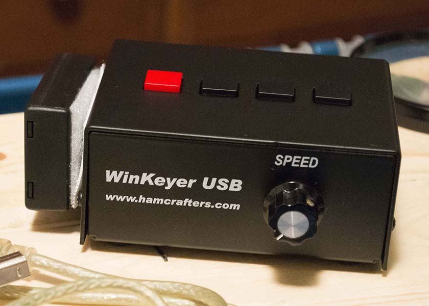
Assembled WinKeyer USB with the battery mounted on the side
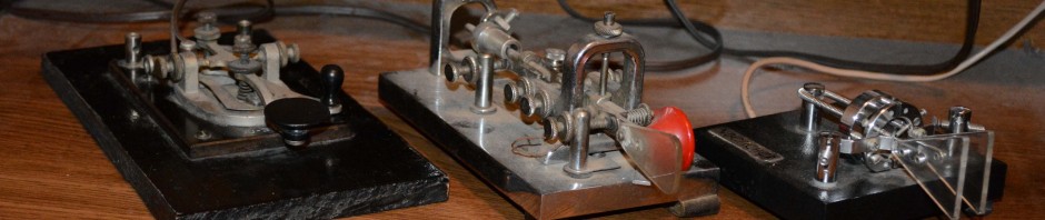
I needed a CW interface between my Mac computer and TS-990 transceiver. It needed to be compatible with contest logging software, select push-to-talk, and transmit CW. Before I had used LPT1: on a PC, but needed to move to a USB interface. After talking to a few others and searching on line, WinKeyer USB appeared to be a good option.
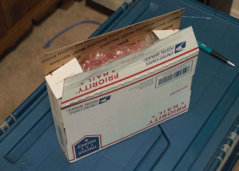
WinKey US Box as received
The kit arrived on Friday and I printed out the online assembly instructions.
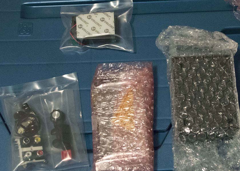
Parts fresh out of the box and still all nicely wrapped up
Saturday afternoon, I set out the tools, checked the parts against the parts list, and re-read the instructions.
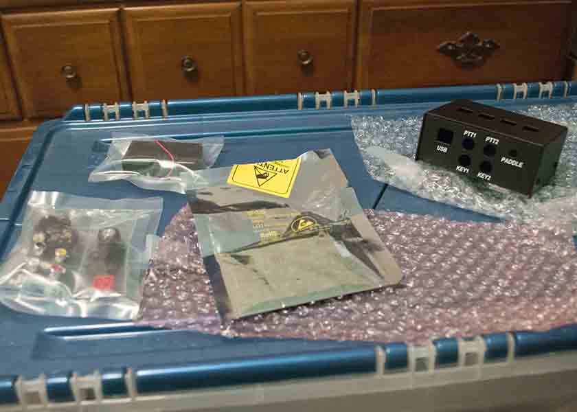
Another view of the same parts
Verified I had all the parts in my work area. I noticed that the paddle connector came already attached.
Work area before getting started (the before picture)
Set out the tools. (I had to make one extra trip to get a pair of scissors to open the packages.) The tools included a soldering iron, small flat head screwdriver (for putting on the knob), small Phillips screwdriver, something to be another pair of hands, and some fine solder.
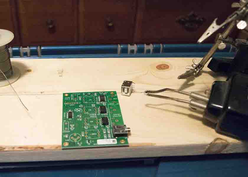
Next step was to mount the USB connector, fold back the larger case stubs to hold it in place, and carefully solder the 4 small pins. These were the smallest and closest together of all the pins to be soldered. I did not do a very good job with these. I got the board too hot, and put too much solder on them. Fortunately, they were not shorted and nothing was damaged.
The small speaker was pushed into the board, being careful to point the positive listed on its’ paper covering in the right direction.
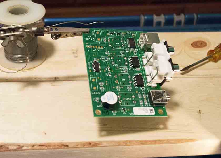
Shows the USB connector in top right, 4 RCA plug piece mounted on right center, and speaker in lower left with the paper cover still attached. In the center, the soldering I did to connect the 4 switches can be seen.
Once I got over my poor attempt at soldering the USB connector, I moved on to attaching the switches. These pushed into their holes on the board and almost felt like they snapped into place. I did bend one of the bins on one of the switches, but it was easy to bend back.
After soldering the switch pins (4 switches with 4 pins each), the white 4-connector RCA plug assembly was mounted and its’ pins were soldered.
Next, the four push button caps were snapped onto the to of the buttons. There were 3 black caps and one red cap. the Red cap went on the left most button with the buttons facing up and the RCA plugs facing away from me.
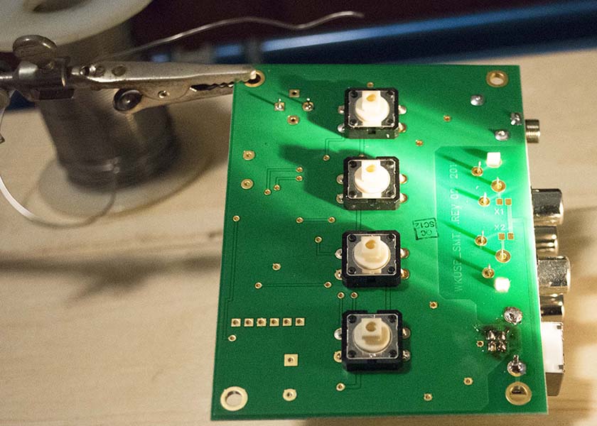
the back side has the 4 switches. On the bottom left is my poor soldering job when mounting the USB connector. On the center right, the 4 RCA plug assembly is mounted to the board, but not yet soldered.
The kit came with a 14 inch piece of wire. This was cut into two 7 inch wires for connecting the speed knob.
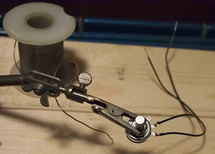
Wires soldered to the speed control
First these wire were connected to the know, and then soldered to the board.
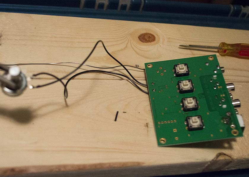
Speed control wires are soldered to board. To the left of the top switch in the picture are two solder connections for the speaker. On the right side, the RCA plug connections are now soldered.
Then the battery case wires were soldered to the board, and all the soldering was done.
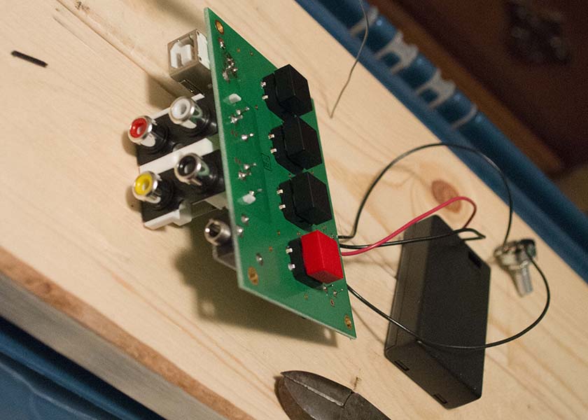
Battery box is attached.
Four screws were provided to secure the PC board to the top of the case. Then the knob was fastened to the bottom part of the case.
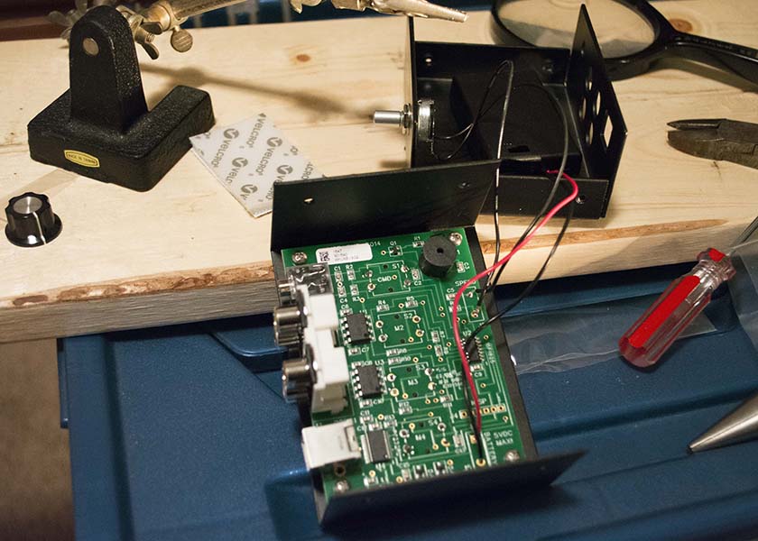
Circuit board is mounted to the top part of the case with 4 Phillips screws. The speed control is mounted to the bottom part of the case.
The battery was supposed to go inside the case. I wanted to have easy access to the battery. My experienced is that batteries typically run down in the middle of a good run during a contest, and I wanted to easily be able to swap them out for new ones. The supplied Velcro was put on the outside of case. I may go back and drill/snip a hole in the case to run the battery wires out.
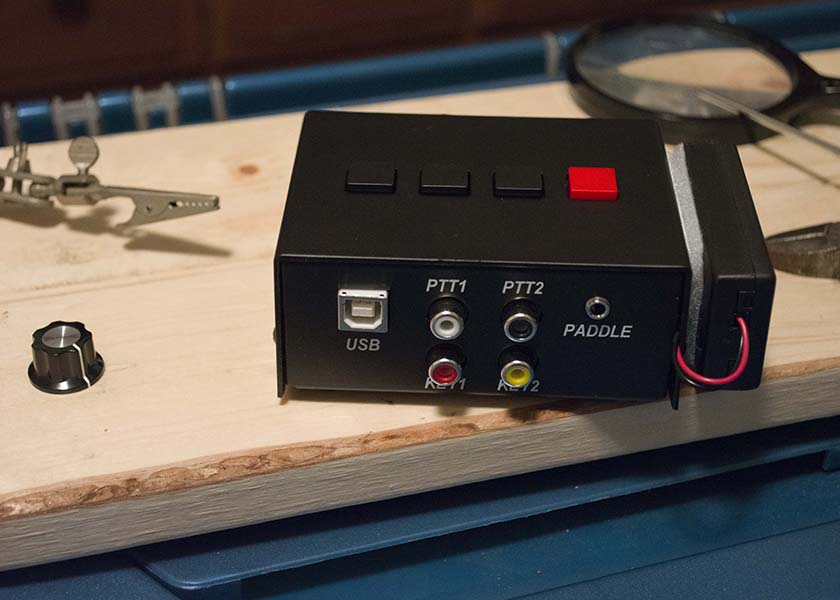
This is the back side of the completed kit. I choose to run the battery wires out of the back of the case and used the included Velcro to attach the battery case to the side.
The final part of assembling the keyer was to attach the knob to the shaft.
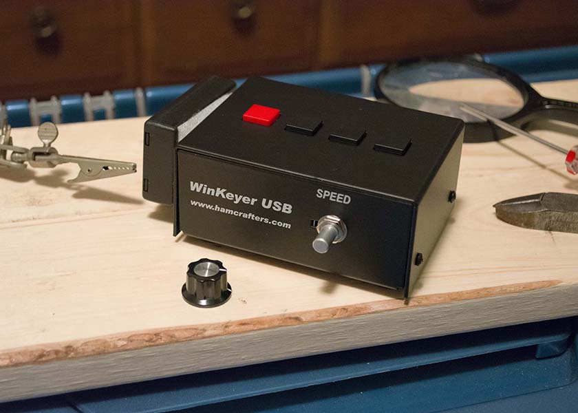
Th front of the WinKeyer just before attaching the knob. The know has a small flat head set screw.
It takes 3 AAA batteries. When these were put in, it sent an “R” as stated in the instructions. Using a USB cable that I had laying around, I connected it to my Mac. The MacWinKeyer driver software appeared to work. I was able to key it to tune, and to send text as I typed. Even with my poor soldering on the USB connector, it seems to be working fine.
Next step is to connect it to the transceiver and test it with some logging software.