After looking around for a portable satellite antenna rotator , I came across the School Amateur Radio Club Network website with instructions on how to build one for a low cost using an Arduino. Their site has excellent instructions. Below are pictures and descriptions of my experience building this fun project.
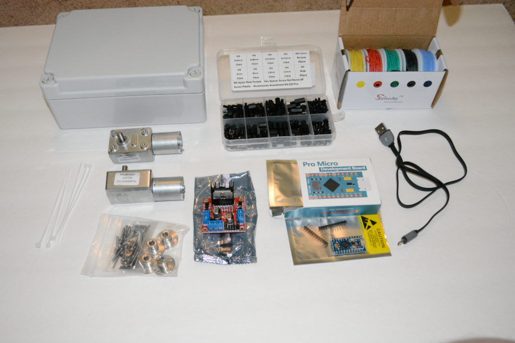
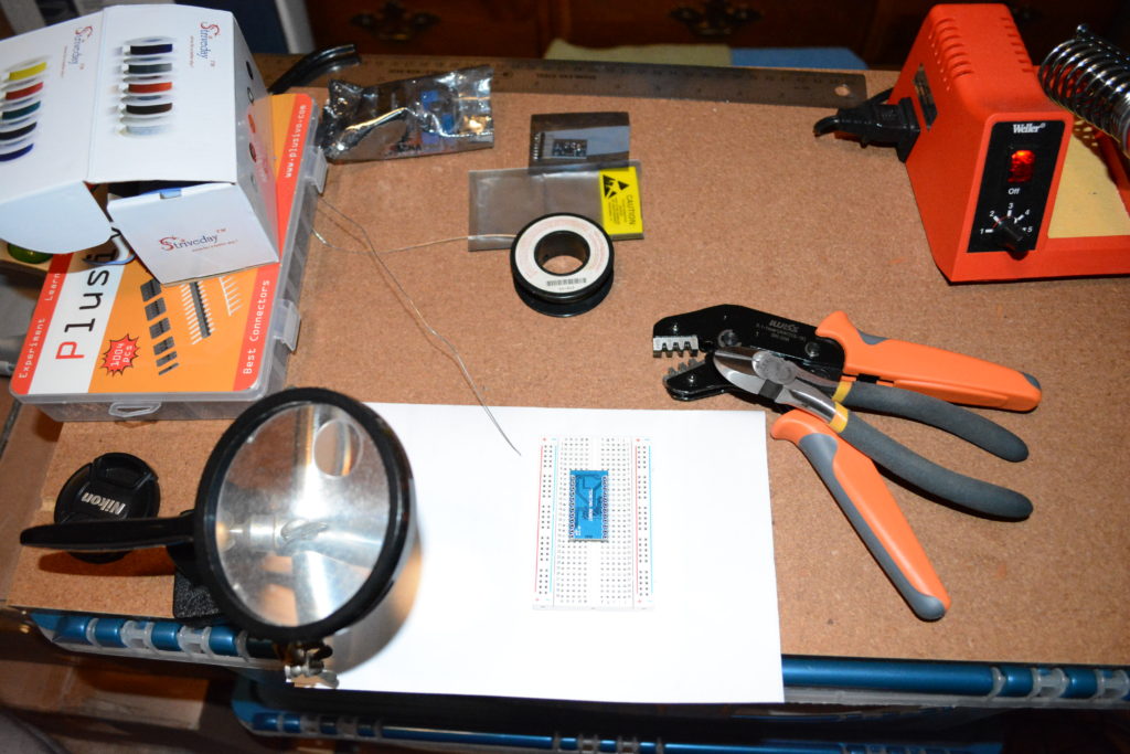
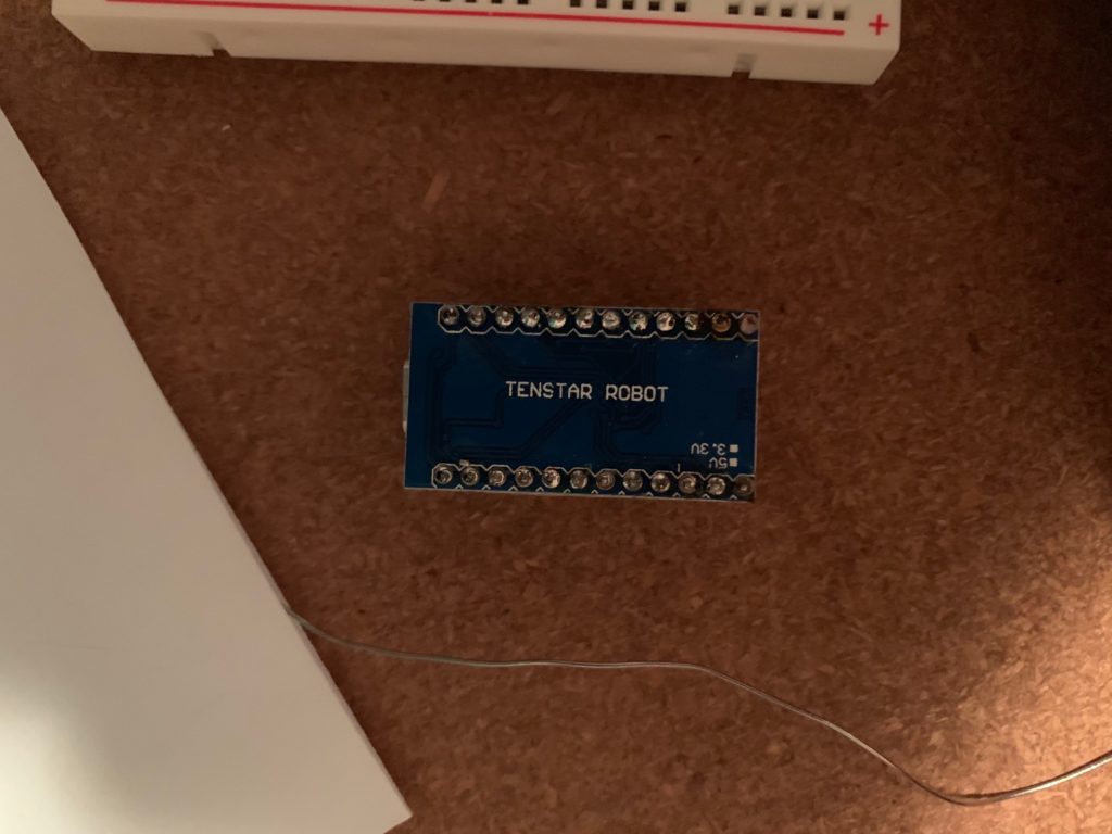
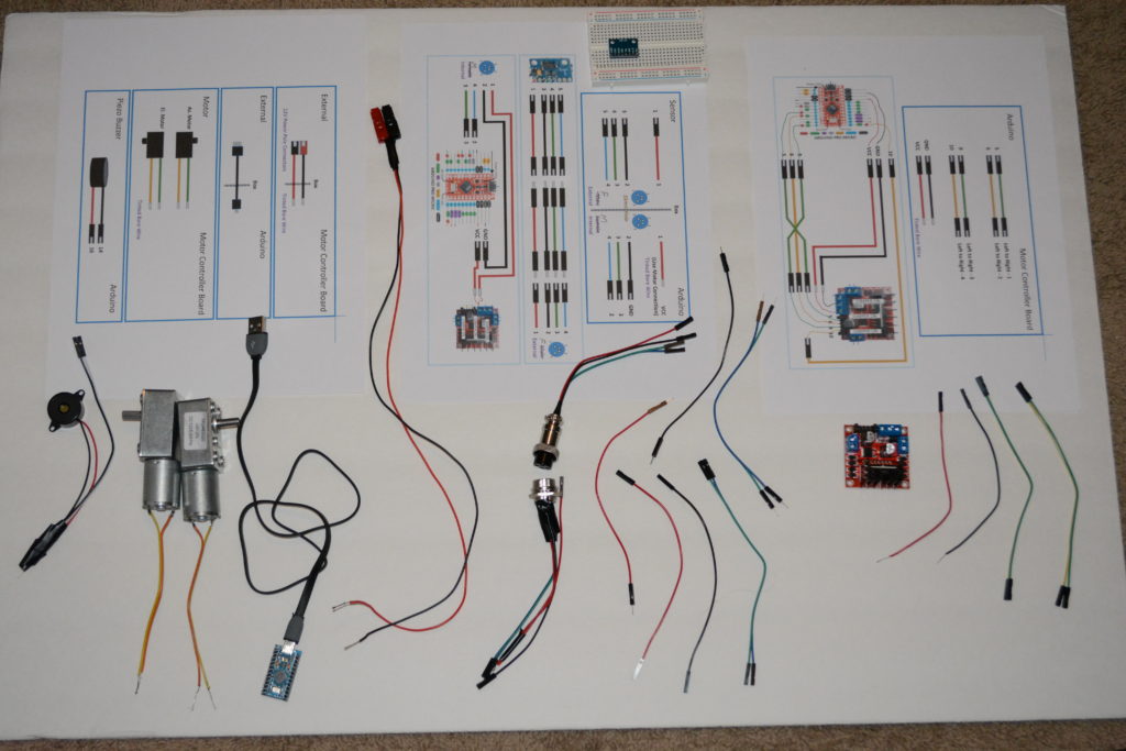
The parts above include the Pro Micro Arduino. Just below the box is one of the ones that came in the package. To the left of it is the motor controller board. It will control the 2 motors. Below the motors are some mounting parts to connect the motor shafts to the antenna and tripod.
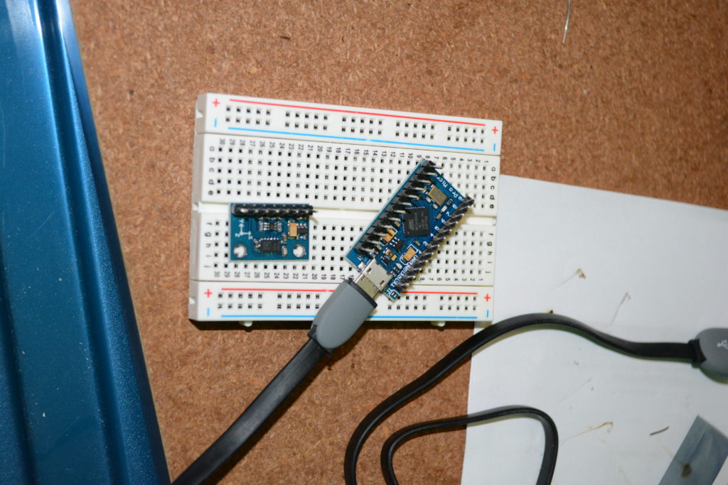
The Arduino software was downloaded. I did a quick test, loading a minimal example program and verifying that the board worked & that the computer could talked to it.
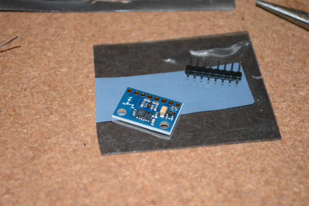
The Magnetometer / Accelerometer board took a few weeks to come after ordering.
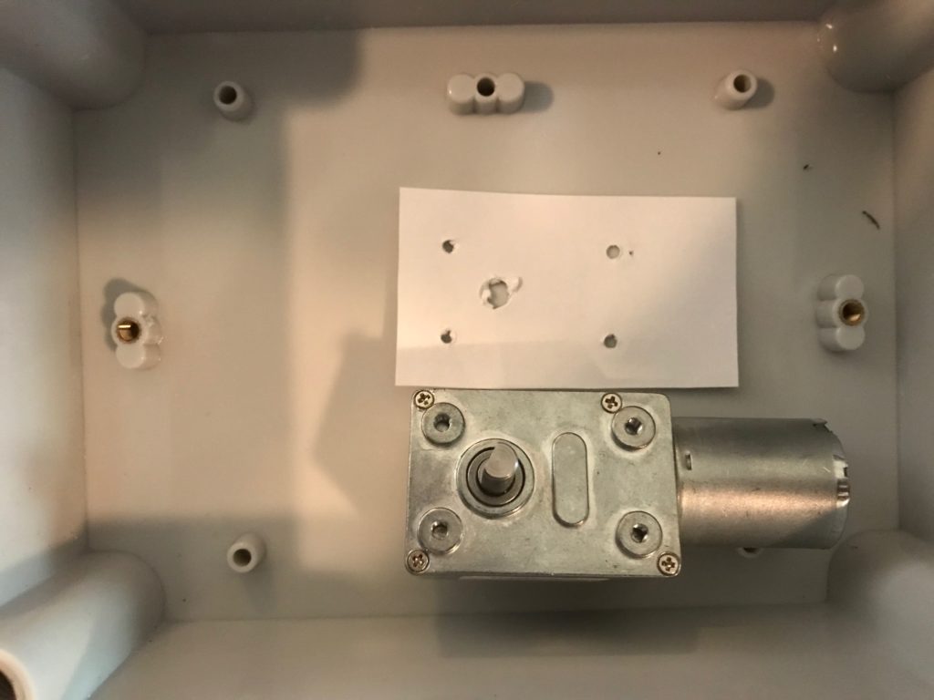
Used an index card and a pointy screwdriver to make a template for drilling the holes in the case.
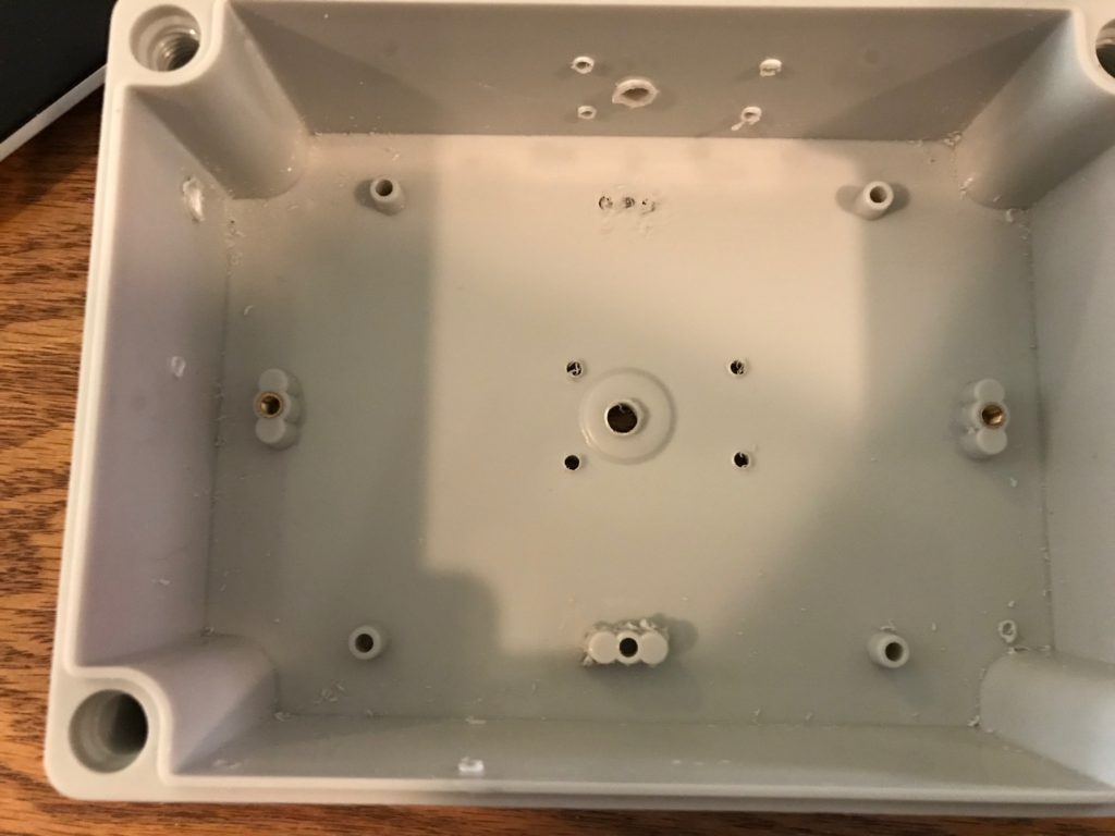
After carefully measuring multiple times to center each shaft, the holes were drilled for the motors, motor controller board, the Arduino. However, the box had these raised areas for screw attachments that precluded the azimuth motor from fitting properly in the box. The top center part of the picture above shows where one of the raised areas had to be ground off.
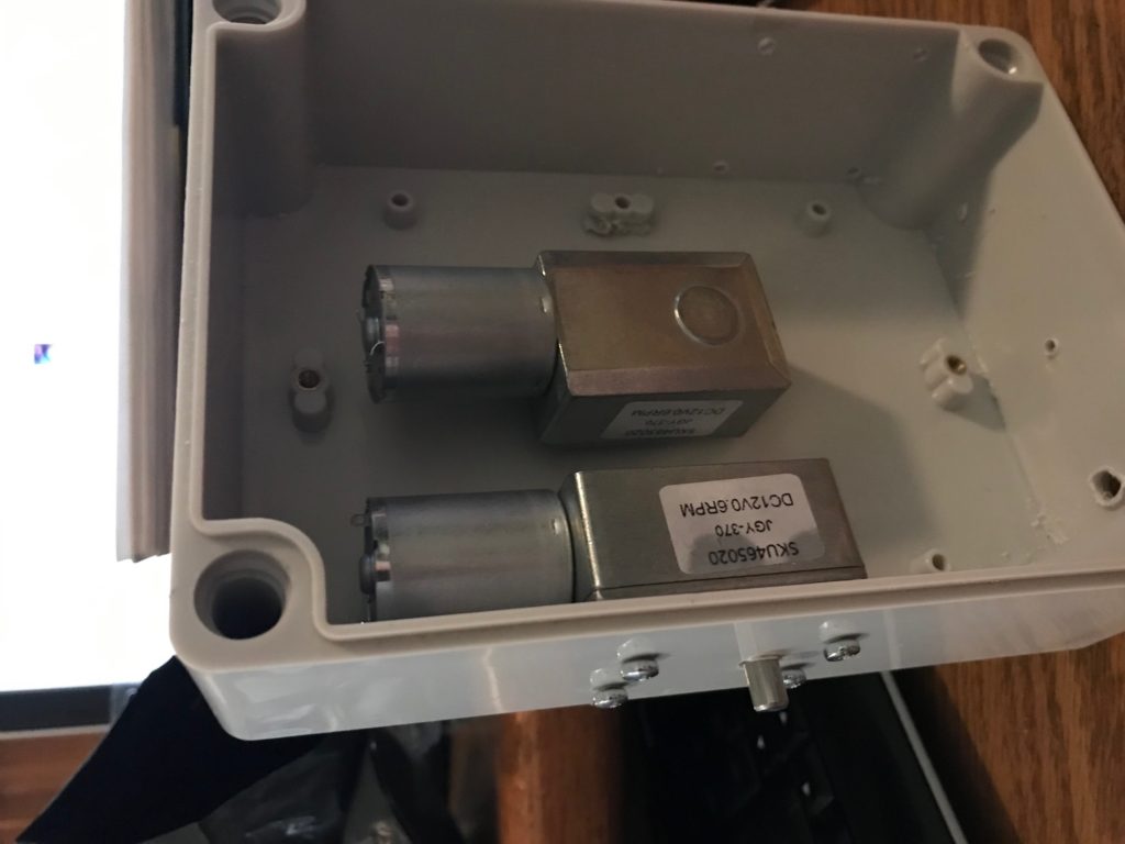
After re-working the box, the motors fit well. The holes drilled from the template are just right.
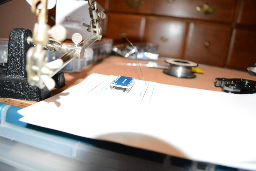
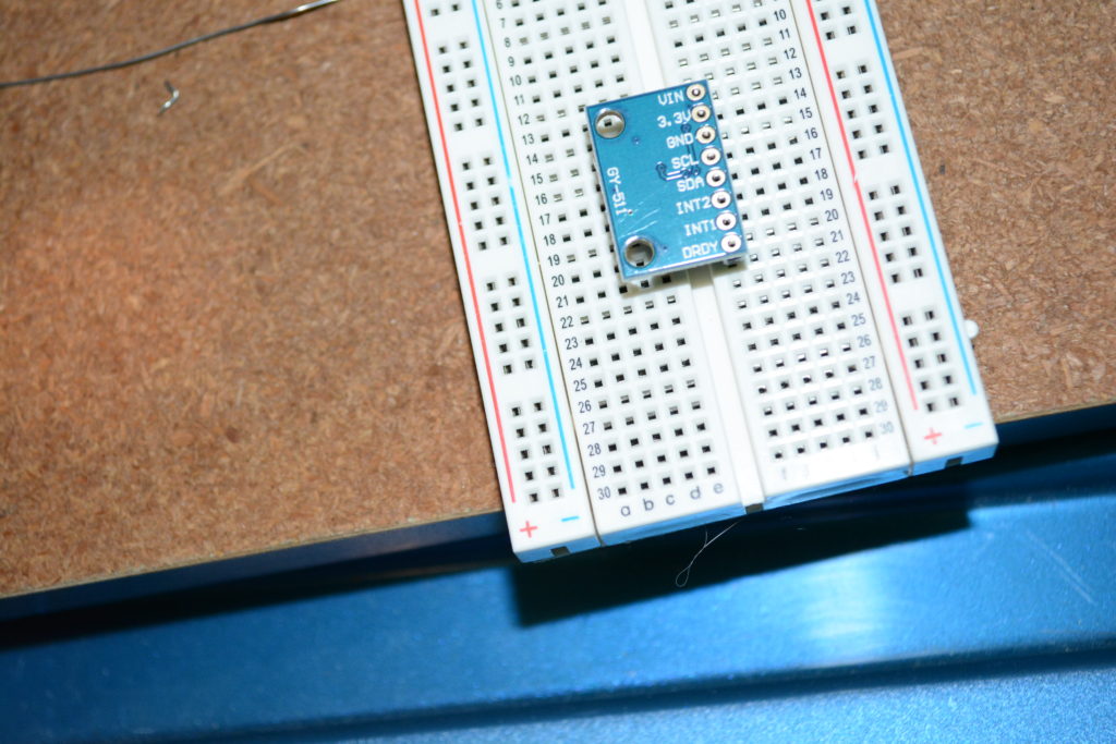
I decided to use the pins and push on wires rather than soldering wires directly to the Arduino and magnetometer boards. Above, the board has the pins pushed onto the board and the other end of the pins are pushed into the breadboard to hold everything in place.
Well, that did not go so well. Most of it looks good, but some of the pins pulled away and the soldering job is not the best. I had better not give up my day job…
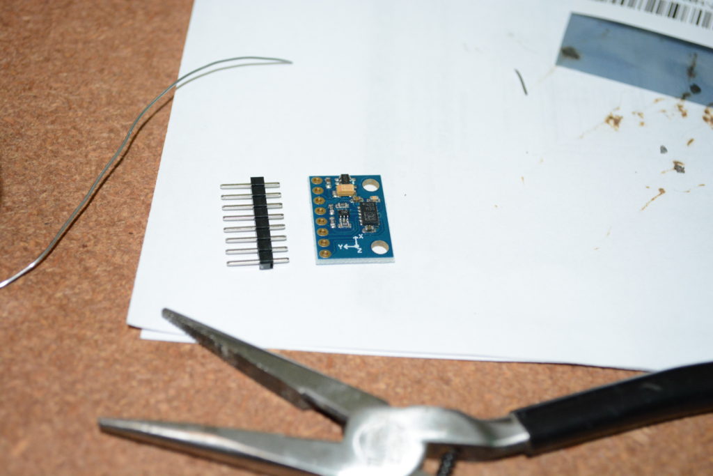
Ok, let’s try this again. Next is the magnetometer / accelerometer board.
Once again, used a breadboard to hold the pins in place even though the pins were only on one side of the board.
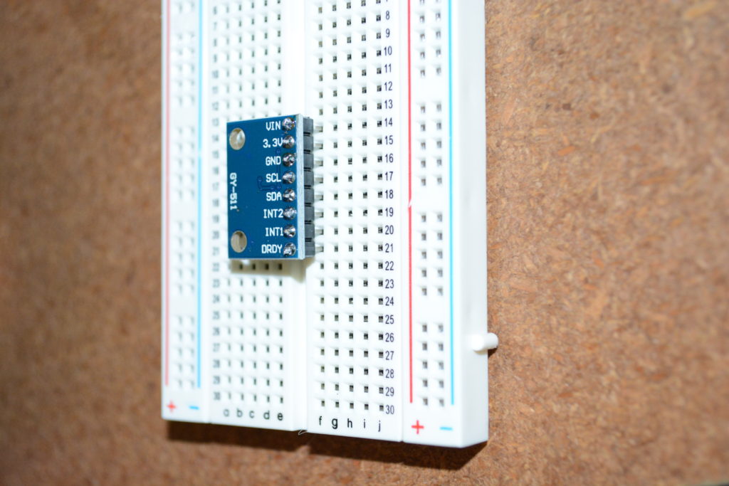
That went much better. I am happy with this soldering job.
Now these are ready to be connected.
Drew out the wires and made any remaining connectors. In the of the above picture is a 4-pin DIN connector, which is used to connecting the Magnetometer / Accelerometer board.
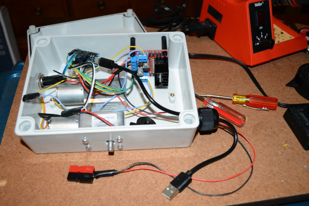
Mounting motor controller board (upper right of case above) had similar issues as the motors had. The case had raised area. Stand off mounting had to be longer than planned to make it fit past the bump. The wires were connected. The Arduino board was left floating – without any mounting. On the bottom right of above picture, the USB connector and 12V power pole connectors are routed out of the box.
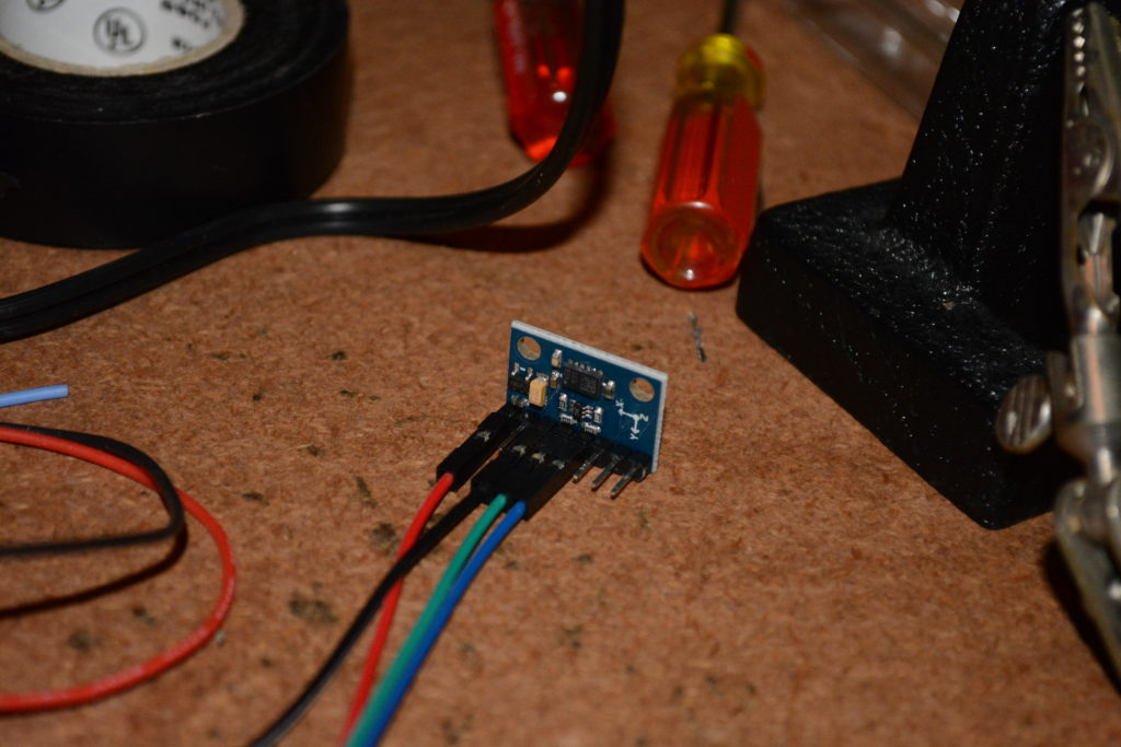
The wires were attached to the Magnetometer / Accelerometer board.
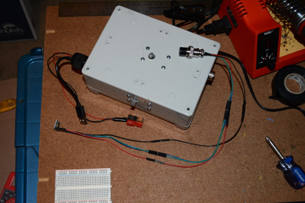
With the wires connected, the box was closed up. Performed a quick test to verify the USB cable was working and the Arduino board was still working.
The next steps are: (1) calibrate the Magnetometer, (2) attach the azimuth shaft (on the side to the bottom left of the above picture) to a tripod, (3) attach the elevation motor shaft (coming out of the top of the box) to the boom for the Arrow Antenna, and (4) attach the Magnetometer / Accelerometer board to the boom.
To be continued…